GP
Great PlasticsEngineering Materials & Custom Parts
Plastic part design guide
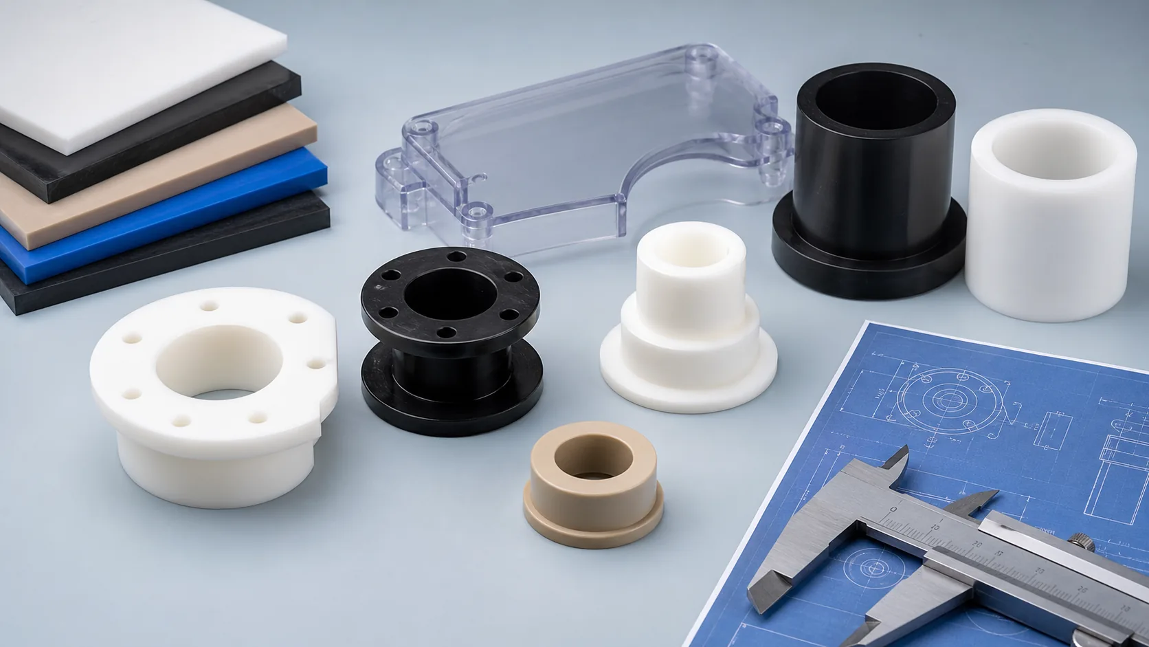
Design engineering plastic parts around material behavior and manufacturing route.
Use this guide to prepare plastic parts for machining, cutting, 3D printing or injection molding by reviewing material, wall thickness, radii, holes, tolerance, finish and RFQ details before production.
Short answer
A good plastic part design starts with how the part will be used and how it will be made.
Plastic parts are not metal parts with a different material callout. They can creep under load, expand with heat, absorb moisture, shrink during molding, warp after machining and deflect under clamping. The right design reduces unnecessary precision, protects functional features and gives the supplier enough information to choose a practical manufacturing route.
Design priorities
Set requirements before choosing the material or process.
| Requirement | Design implication | What to show on the drawing |
|---|---|---|
| Temperature | Heat affects stiffness, expansion, creep, machining stability and molding shrinkage. | Operating range, peak temperature and whether the part is loaded while hot. |
| Chemical exposure | Material choice, seals, wall thickness and stress-cracking risk may change. | Chemical name, concentration, exposure time and cleaning method. |
| Load and wear | Ribs, bosses, bearing surfaces, fiber-filled grades or low-friction materials may be needed. | Load direction, moving surfaces, mating material and expected service life. |
| Fit and assembly | Holes, inserts, snap features, press fits and mating faces need realistic tolerances. | Critical dimensions, datum faces, fastener type and assembly sequence. |
| Appearance | Visible faces, tool marks, sink marks, gate marks, polish and color should be separated from hidden features. | Cosmetic surfaces, acceptable marks, color and texture expectations. |
Core design rules
Plastic part details that affect cost, quality and manufacturability.
Wall thickness
Keep wall thickness consistent where possible. Thick sections can cause sink or long cooling in molding, while thin walls can flex, chatter or warp during machining.
Radii and corners
Add internal radii to reduce stress and allow tool access. Sharp internal corners increase cost and may be impossible in machined parts.
Ribs and support
Use ribs to improve stiffness without creating heavy sections. Review rib thickness, root radii and machining access before release.
Holes and bosses
Bosses, inserts, tapped holes and press fits need material-specific review because plastic threads, creep and cracking behave differently from metal.
Draft and release
Molded parts need draft and gate/ejector planning. Machined parts may not need draft but still need tool access and clamping surfaces.
Tolerance strategy
Apply tight tolerances only to features that control fit, motion, sealing or inspection. General dimensions should reflect plastic movement.
Design review workbench
Capture the few inputs that decide whether a plastic part is easy or risky to make.
What the supplier needs to understand first
Before a plastic part is quoted, the design should separate the function from the shape. This helps decide material, stock form, machining route, molding risk, inspection scope and which tolerances actually need tight control.
- Function: bearing, spacer, seal, cover, fixture, electrical insulator, wear component or structural part.
- Route stage: prototype, design validation, low-volume production, repeat production or tooling review.
- Design risk: thin walls, thick sections, ribs, bosses, inserts, sealing faces, cosmetic faces or high-load threads.
- Environment: heat, chemicals, moisture, UV, cleaning, speed, load, friction, electrical or food/medical contact needs.
Failure prevention
Catch common plastic part problems while the drawing is still easy to change.
| Problem seen in use | Likely design cause | Better design response |
|---|---|---|
| Warping or poor flatness | Heavy one-sided material removal, uneven wall sections, molded shrinkage imbalance or unsupported thin areas. | Balance material removal, add support, separate cosmetic flatness from functional datums and relax non-critical areas. |
| Cracks around holes or inserts | Sharp corners, undersized bosses, press-fit stress, aggressive tapping or fasteners too close to an edge. | Add radii, increase boss support, use inserts where needed and define fastener load instead of copying metal details. |
| Loose fit after service | Creep, moisture absorption, thermal expansion or plastic selected only from room-temperature stiffness. | Design around real temperature, load time, humidity and mating material; keep fit tolerances tied to function. |
| Poor surface appearance | Cosmetic faces mixed with machined faces, gate/ejector marks, polishing expectation not stated or clear plastic stress marks. | Mark visible faces, acceptable tool marks, polish needs, color and protected surfaces on the drawing. |
| High quote cost | Unnecessary tight tolerances, deep pockets, sharp internal corners, hard-to-source material or route mismatch. | Keep tight control on functional features, open non-critical geometry and compare machining, cutting, printing and molding early. |
Manufacturing route
Design choices change depending on how the part will be made.
| Route | Design focus | Common design risk | Best next step |
|---|---|---|---|
| CNC machining | Tool access, workholding, stock form, radii, flatness, burrs and critical tolerances. | Metal-style tolerances, deep pockets, thin walls and poor datum planning. | Review CNC plastic machining |
| Custom cutting | Sheet/rod/tube size, edge finish, cut allowance, deburring and downstream operations. | Expecting cut blanks to meet precision-machined feature requirements. | Review custom plastic cutting |
| 3D printing | Build orientation, layer strength, support marks, minimum features and material behavior. | Assuming printed material behaves like machined stock or molded resin. | Review engineering plastic 3D printing |
| Injection molding | Wall consistency, ribs, bosses, draft, gates, sink, shrinkage and ejection. | Freezing tooling before part geometry, resin and production volume are validated. | Review injection molding |
Design workflow
Move from idea to quote-ready plastic part.
Define the application
State heat, chemical, load, wear, electrical, moisture, cleaning and service-life conditions before choosing material.
Choose the route
Decide whether the project is better suited to machining, cutting, 3D printing, molding or a staged validation path.
Refine the geometry
Review walls, radii, ribs, holes, bosses, inserts, datum faces, cosmetic faces and inspection features.
Prepare RFQ files
Send drawing, 3D model, material target, quantity, tolerances, finish needs, inspection notes and lead-time goal.
Material guidance
Material choice affects every design decision after it.
| Material direction | Design advantage | Design caution |
|---|---|---|
| POM / acetal | Good dimensional stability and machinability for mechanical parts. | Review chemical exposure, temperature and bearing/wear conditions. |
| Nylon | Useful for wear, impact and tough mechanical parts. | Moisture can change dimensions; avoid overly tight fits without review. |
| PTFE and fluoropolymers | Low friction and chemical resistance. | Creep and softness affect threads, thin sections, compression and tolerance. |
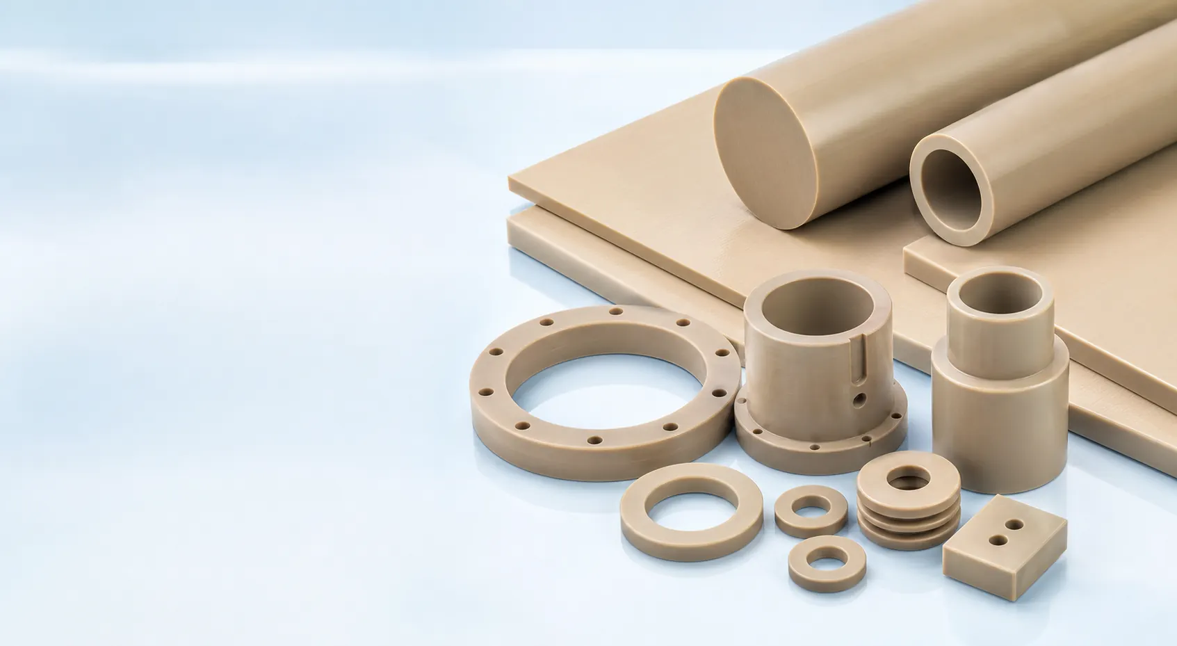
| PEEK, PPS, PEI and PAI | High heat, chemical, electrical or structural performance. | Higher material cost makes yield, revision control and drawing accuracy important. |
| PC, acrylic and transparent plastics | Good for covers, guards, windows and visual parts. | Stress cracking, visible marks, polish, holes near edges and chemical exposure need review. |
Drawing review
Make the drawing separate function from convenience.
Plastic part drawings should tell the supplier what must work, what may be adjusted for manufacturing, and what can be treated as general geometry. This reduces quote uncertainty and helps prevent unnecessary cost.
- Mark functional surfaces, datum faces, sealing areas, bearing locations and cosmetic faces.
- Call out material grade, color, stock form, substitution limits and documentation needs.
- Define whether holes are clearance, tapped, insert-ready, press-fit or alignment features.
- State whether the part is for prototype, validation, fixture use, replacement or repeat production.
RFQ checklist
Send design information that makes review faster and more accurate.
| RFQ input | Why it matters |
|---|---|
| 2D drawing and 3D model | The model shows geometry; the drawing shows critical dimensions, notes and inspection intent. |
| Material or performance target | Design rules change with stiffness, creep, heat, chemicals, moisture and wear. |
| Manufacturing route preference | Machining, cutting, printing and molding have different wall, radius, tolerance and finish rules. |
| Quantity and revision stage | Prototype, pilot and production parts should not carry the same cost and tooling assumptions. |
| Critical tolerances and surfaces | Quote accuracy improves when tight requirements are tied to real function. |
| Operating environment | Temperature, chemicals, load, wear, cleaning and electrical requirements drive material and geometry decisions. |
Related pages
Continue from design guidance to material and production review.
FAQ
Questions engineers ask before designing plastic parts.
What should a plastic part design guide cover?
A useful guide should cover material selection, wall thickness, radii, holes, bosses, ribs, tolerances, surface finish, manufacturing route and RFQ information.
How is plastic part design different from metal part design?
Plastic parts move more with temperature, moisture, stress and load. Designs should account for creep, shrinkage, warpage, draft, radii, clamping and realistic tolerances.
Should a plastic part be machined or molded?
Machining often fits prototypes, low-volume parts and precision features. Molding can fit repeated production once material, geometry, volume and tooling risk are clear.
Why does wall thickness matter in plastic part design?
Wall thickness affects cooling, sink, stiffness, machining stability, warpage, weight and cost. Consistent thickness usually makes a part easier to manufacture.
Can tight tolerances be used on plastic parts?
Yes, but tight tolerances should be limited to functional features. Plastic movement from heat, moisture, stress and load should be considered before applying metal-style tolerances.
What should be included in a plastic part RFQ?
Send a 2D drawing or 3D model, material or performance target, dimensions, tolerances, quantity, application environment, finish needs, inspection requirements and lead time.
Design and manufacturing review
Send your plastic part drawing before locking the material or route.
Share the model, drawing, material target, quantity, tolerance notes, use environment and preferred manufacturing route. Great Plastics will review whether machining, cutting, 3D printing or molding is the stronger path.