
Engineering Plastic Manufacturing Services
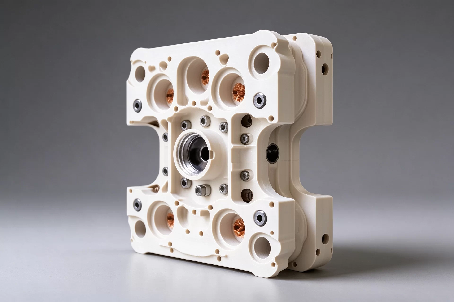
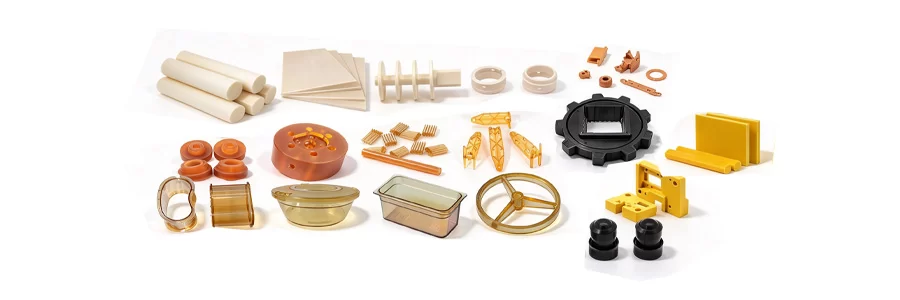
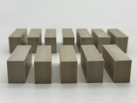
Great Plastics supports custom engineering plastic parts made from PEEK, PPS, PI, PAI and PEI.
We help evaluate material requirements, part geometry, manufacturing routes and inspection needs to align each project with its functional and production requirements.
What We Manufacture
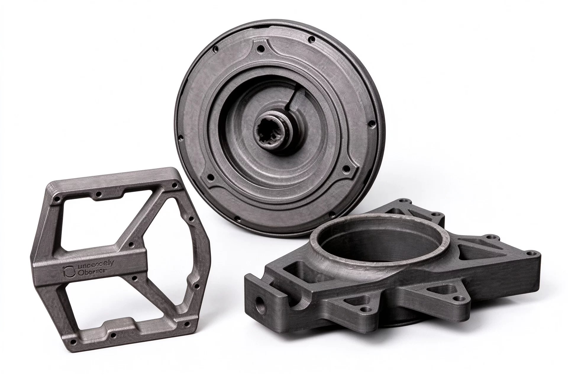
Custom Engineering Plastic Parts
Manufacturing Routes
Choose the Right Manufacturing Route
The right manufacturing route depends on part geometry, material requirements, production stage and inspection needs.
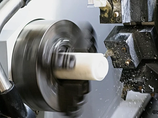
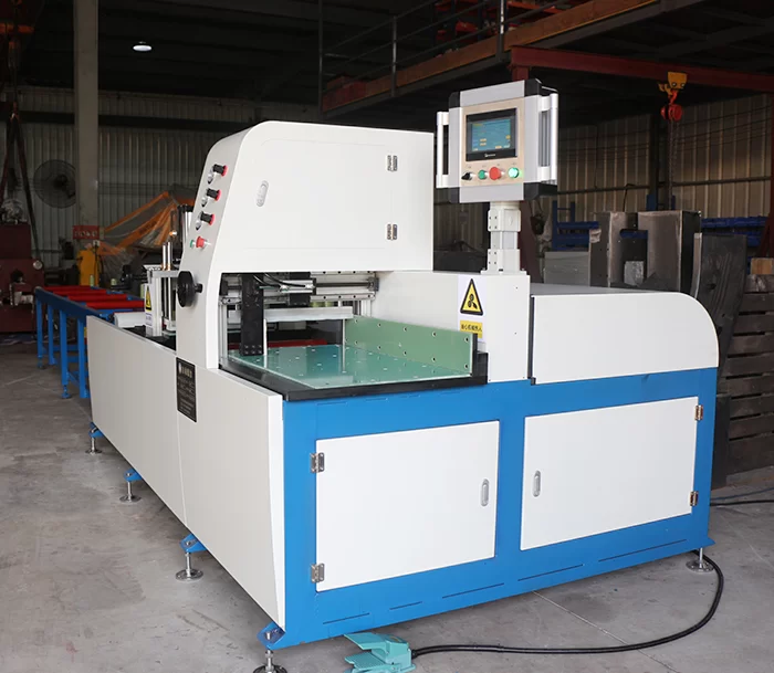
CNC Plastic Machining
Best for: precision parts, prototypes, bushings, fixtures and replacement components.
When to explore: start here when the part has defined geometry, critical dimensions, or must be made from stock shapes without tooling.
View Route
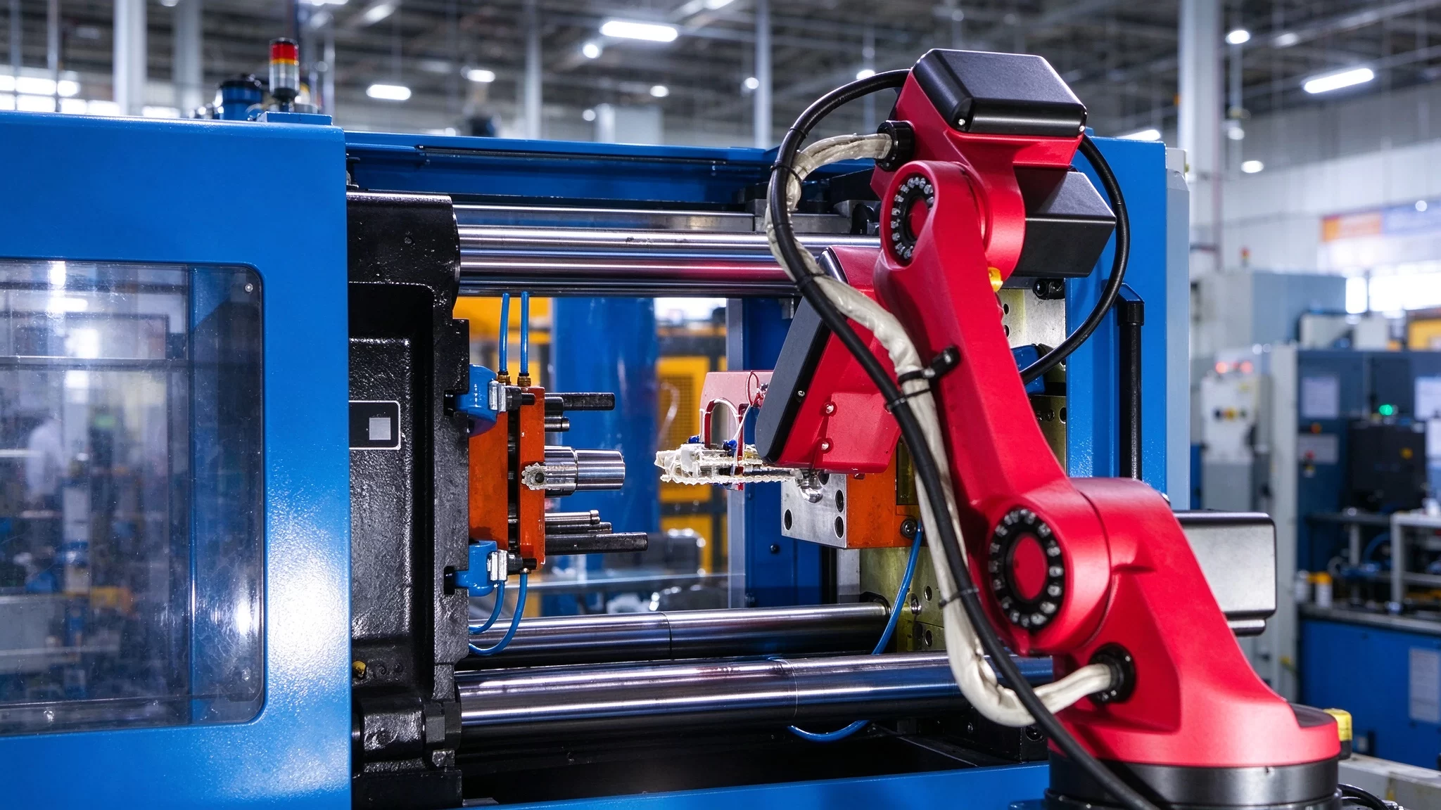
Injection Molding
Best for: repeat demand after resin, DFM and tooling assumptions are stable.
When to explore: consider it for recurring quantities once the design and material are established.
View Route
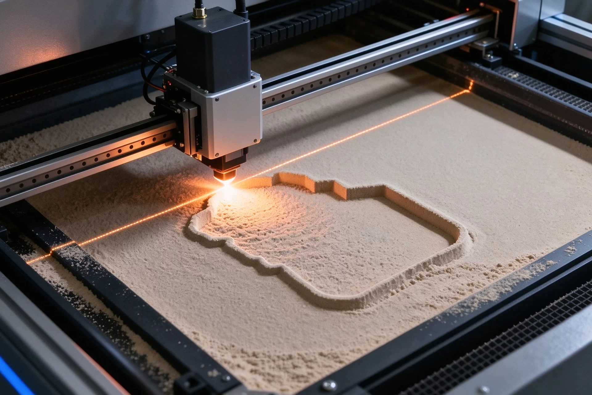
3D Printing
Best for: functional prototypes and selected high-performance printed parts.
When to explore: choose it for fast iteration, complex geometry and parts suited to additive processes.
View Route
compare
Not sure which manufacturing process to use?
Most engineers start with material and volume. Here’s a quick comparison.
| Service | Lead Times | Tolerances | Max Part Size |
|---|---|---|---|
| Injection Molding | 1–20 days | ±0.003 in. | 18.9 in. × 29.6 in. × 8 in. |
| CNC Machining | 1–7 days | ±0.002 in. | 22 in. × 14 in. × 3.75 in. |
| 3D Printing | 1–7 days | ±0.002 in. | 29 in. × 25 in. × 21 in. |
Five High-Performance Plastics
Material Selection Starts With the Application
Great Plastics focuses on PEEK, PPS, PI, PAI and PEI. The appropriate grade and manufacturing route depend on operating conditions, part geometry and functional requirements.
Engineering Review
Review the Requirements Before Production
Great Plastics focuses on PEEK, PPS, PI, PAI and PEI. The appropriate grade and manufacturing route depend on operating conditions, part geometry and functional requirements.
For wall thickness, holes, threads, fits and surface finish, see the Design Guide. Open the Design Guide→
How a Project Moves Forward
From Requirements to a Manufacturing Plan
A typical project conversation moves through the steps below before production. Timing and scope are confirmed for each part individually.
Understand the Application
Clarify the functional requirements and operating conditions the part must meet.
Review Material & Design
Consider the material, part geometry and critical features together.
Evaluate the Route
Identify a suitable manufacturing route for the geometry and production stage.
Clarify Quote & Inspection
Confirm quotation details, tolerances, finish and inspection requirements.
Buyer questions
Frequently Asked Questions
Discuss Your Next Engineering Plastic Part
Share your drawing, target material, operating conditions and quantity requirements.
Great Plastics can review the available information and help identify a suitable next step for your part.
