GP
Great PlasticsEngineering Materials & Custom Parts
Plastic machining guide
Design machined plastic parts around material movement, heat and realistic tolerances.
Use this guide to review machinable plastics, CNC process risks, drawing notes, tolerance strategy and RFQ inputs before sending engineering plastic parts for machining.
Short answer
Plastic machining succeeds when the drawing treats polymers differently from metal.
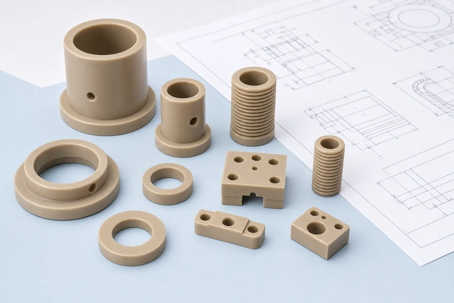
Engineering plastics can be milled, turned, drilled, routed and tapped, but they expand, absorb moisture, relax internal stress, soften with heat and deflect under clamping. The strongest machining plan starts with the material and service environment, then assigns tight tolerances only to the features that control fit, sealing, motion or assembly.
Material selection
Choose machinable plastics by function, not only by price or availability.
| Material family | Machining behavior | Good fit | Watch before quoting |
|---|---|---|---|
| POM / acetal | Clean cutting, dimensionally stable and predictable for many precision parts. | Bushings, rollers, gears, guides, spacers and low-friction parts. | Temperature limit, chemical exposure and brand/grade requirements. |
| Nylon | Tough and wear resistant, but moisture can affect dimensions and stiffness. | Wear pads, rollers, wheels, sleeves and impact-resistant mechanical parts. | Humidity, tight fits, creep, swelling and post-machining dimensional change. |
| PTFE and fluoropolymers | Soft, slippery and prone to creep; sharp tools and support are important. | Seals, seats, chemical contact parts, low-friction components. | Thin walls, compression, burrs, tolerance drift and handling deformation. |
| PEEK, PPS and PEI | High-performance materials can machine well but deserve careful yield and stress planning. | High-temperature, chemical, electrical, aerospace, semiconductor and medical/lab components. | Stock cost, annealing review, edge chipping, documentation and inspection needs. |
| Acrylic, PC and clear plastics | Can produce clean visual parts, but cracking, stress marks and optical finish need attention. | Guards, windows, covers, light pipes, inspection fixtures and display parts. | Polishing, stress cracking, coolant compatibility, holes near edges and cosmetic faces. |
| HDPE, UHMW and PP | Soft or gummy behavior can create burrs, deflection and less crisp edges. | Liners, wear strips, low-friction slides, food-contact style parts and simple fixtures. | Flatness, thermal expansion, clamping marks, burr control and tolerance expectations. |
Machining decisions
Six questions to answer before the drawing goes out for quote.
Which features are functional?
Mark sealing faces, bearing fits, mating surfaces, fastener locations and datum features. Leave non-critical features with practical tolerances.
How will the part be held?
Thin plates, soft plastics and round parts can move under clamping. Add stock allowance or fixture-friendly surfaces when possible.
Where can heat build up?
Deep pockets, small holes, slow chip evacuation and dull tools can cause melting, smearing, cracking or rough finish.
Will the material move later?
Moisture, temperature swings, stress relief and heavy material removal can change dimensions after machining.
Is the surface a function?
Cosmetic, sliding, sealing and bearing surfaces need different finish expectations. State the purpose, not just a generic finish callout.
Is machining the right route?
Compare custom cutting, 3D printing and injection molding before over-specifying the part.
Machining guide workbench
Turn a plastic part drawing into quote-ready machining inputs.
Fast drawing risk review
Use this structure when a buyer needs help setting material, tolerance, stock form and machining route before sending a CNC plastic part RFQ.
- Part function: bearing, seal, spacer, fixture, electrical insulator, wear part, housing or replacement component.
- Material target: POM, Nylon, PTFE, PEEK, PPS, PEI, PC, acrylic, HDPE/UHMW or performance-based selection.
- Machining risk: thin walls, deep pockets, long bores, flatness, tight fits, cosmetic faces, burr-sensitive edges or thread load.
- Use environment: temperature, moisture, chemicals, load, speed, mating material, cleaning and inspection needs.
Design rules
Practical DFM checks for machined plastic parts.
| Drawing feature | Good practice | Risk if ignored |
|---|---|---|
| Thin walls and large pockets | Keep walls supported, reduce unnecessary pocket depth and avoid heavy one-sided material removal. | Warping, chatter, poor flatness and broken corners. |
| Sharp internal corners | Use radii that match practical tool access. Mark only truly sharp features as critical. | Higher cost, tool marks, stress concentration and impossible geometry. |
| Deep holes and threads | Confirm thread type, insert option, pilot depth and whether the plastic can hold the load. | Heat buildup, weak threads, tapping defects and poor assembly life. |
| Tight tolerance stackups | Apply tight tolerance to functional datums and fits; keep general dimensions realistic. | High scrap risk, longer inspection time and unstable parts after release. |
| Flatness and parallelism | Review material thickness, stress, clamping method and final use before setting tight flatness. | Parts pass machining but move during storage, assembly or temperature change. |
| Cosmetic surfaces | Identify visible faces, protected faces and allowable tool marks before quoting. | Unexpected machining marks, polishing cost or rejected appearance. |
Tolerance planning
Assign tight tolerances only where the plastic part must function.
| Feature type | Often worth tighter control | Often safe to relax | Drawing note |
|---|---|---|---|
| Bores and shafts | Bearing fits, sliding fits, seal glands, shaft locations and concentric features. | Clearance holes, nonfunctional lightening holes and cosmetic openings. | State mating shaft, fit function and inspection method. |
| Flat faces | Sealing faces, datum faces, mounting pads and parts that stack in an assembly. | Hidden pockets, weight-reduction areas and non-contact surfaces. | Mark datum surfaces and acceptable tool marks. |
| Threads and inserts | Load-bearing threads, repeat assembly, inserts and pull-out requirements. | Temporary fixture holes or low-load covers where clearance fasteners work. | List thread type, depth, insert spec and fastener material. |
| Thin walls | Features that locate a mating part or protect a controlled surface. | Walls that can be thickened, ribbed or relieved without changing function. | Identify areas that can be modified for machining stability. |
| Overall dimensions | Envelope dimensions that control installation, clearance or assembly stackup. | General outside sizes where plastic movement and saw/machining marks are acceptable. | Separate critical envelope from reference dimensions. |
Machining workflow
Turn a plastic part drawing into a quote-ready machining package.
Define the environment
List temperature, chemicals, moisture, load, wear, electrical needs, cleaning method and expected service life.
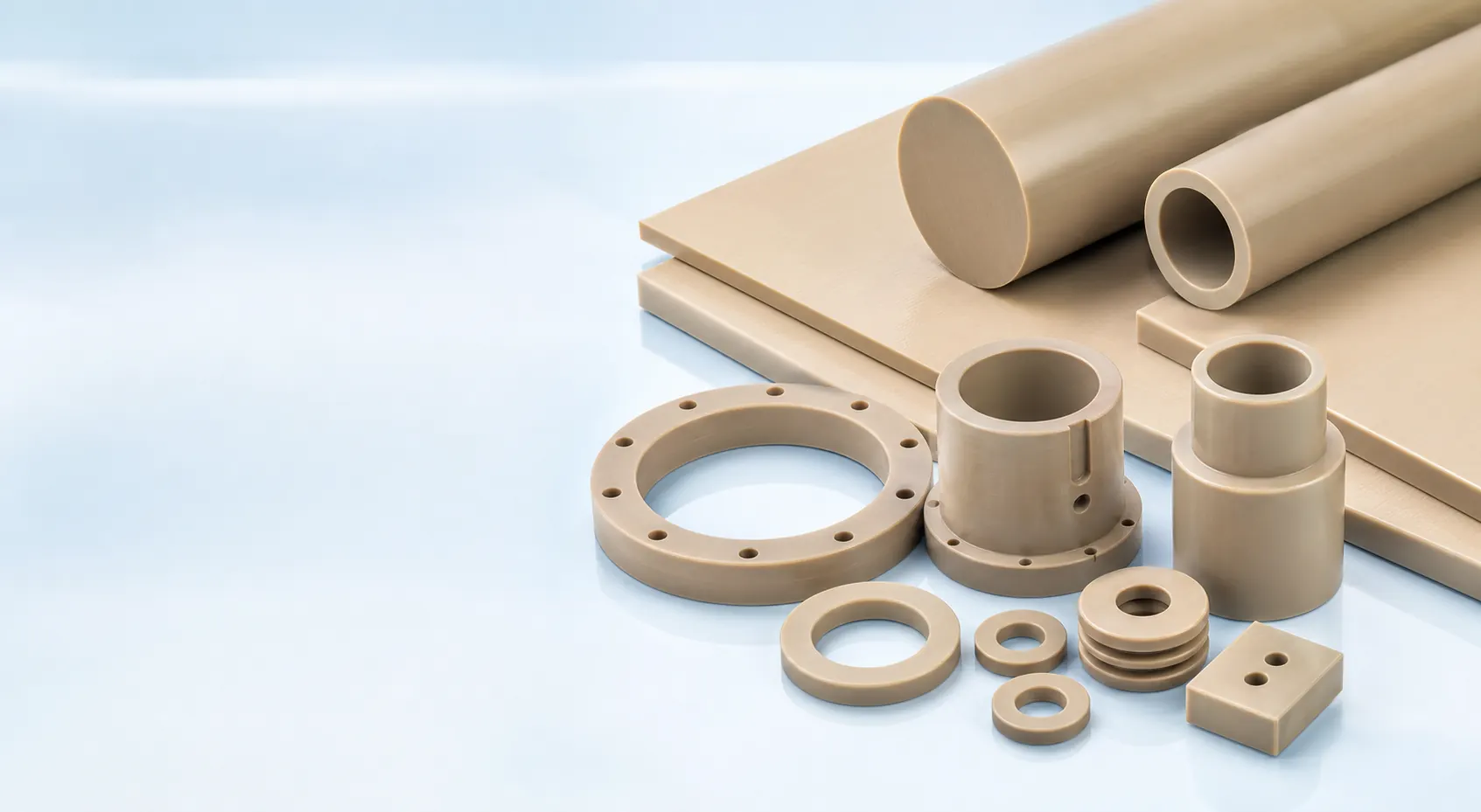
Select material and stock form
Choose sheet, plate, rod or tube with enough allowance for machining, stress review and edge cleanup.
Review geometry and tolerance
Identify critical features, tool access, fixturing surfaces, burr-sensitive edges and inspection requirements.
Choose the production route
Use CNC machining for precision; use cutting, 3D printing or molding when the geometry, quantity or cost target points elsewhere.
Route comparison
Machining is powerful, but not always the first or final route.
| Route | Use it when | Review another route when |
|---|---|---|
| CNC plastic machining | The part needs precise geometry, stock-shape material behavior, holes, pockets, faces or low-volume production. | The part is a simple panel, rough blank, early shape concept or high-volume molded component. |
| Custom cutting | You need rectangles, strips, rod cut-off, tube blanks or simple flat profiles. | The part needs tight datum relationships, threaded holes, pockets or finished bearing faces. |
| Engineering plastic 3D printing | Speed, complex shape or early fit review matters more than final bulk material behavior. | The part needs tight tolerance, sealing faces, final material behavior or smooth machined surfaces. |
| Injection molding | Demand is repeated, resin is validated and tooling cost is justified. | Design is still changing, volume is low or material/application risk is not resolved. |
Drawing review
Make the drawing tell the machinist what must actually work.
A plastic machining drawing should separate critical features from convenient dimensions. That helps the quote focus on the features that affect assembly, motion, sealing, appearance and inspection rather than forcing metal-style precision everywhere.
- Mark datum faces, mating surfaces, sliding surfaces, sealing areas and cosmetic faces.
- Call out material grade, color, stock form, certification needs and any substitution limits.
- State whether holes are clearance, tapped, insert-ready, press-fit or bearing locations.
- Share whether the part is a prototype, replacement part, fixture or repeat production component.
RFQ checklist
Send enough detail to quote machining instead of guessing.
| RFQ input | Why it matters |
|---|---|
| 2D drawing and 3D model | The model explains shape; the drawing defines critical dimensions, notes and inspection. |
| Material or performance target | Machinability, tolerance, finish and cost change sharply between POM, nylon, PTFE, PEEK, PEI and PC. |
| Quantity and revision stage | Prototype, pilot and repeat production parts need different setup and inspection planning. |
| Operating environment | Temperature, chemicals, moisture, wear, load and electrical needs affect material selection. |
| Critical tolerances and surfaces | Quote accuracy improves when tight dimensions are limited to features that control function. |
| Inspection and documentation | First article, dimensional report, material documents or traceability should be confirmed before production. |
Related pages
Move from guide to material or quote review.
FAQ
Questions engineers ask before machining plastic parts.
What plastics are easiest to machine?
POM/acetal, cast acrylic, ABS and many rigid engineering plastics are often easier to machine than soft, gummy or moisture-sensitive materials. The final choice should still match load, heat, chemical and tolerance needs.
Why do plastic parts warp after machining?
Warping can come from internal stress in the stock shape, uneven material removal, heat buildup, moisture, weak fixturing or overly tight flatness expectations. Identify datum faces and critical features before quoting.
Can plastics hold metal-like tolerances?
Some stable plastics can hold tight features, but plastics move with temperature, moisture, stress and load. Critical tolerances should be limited to functional areas and reviewed by material and part geometry.
Is PEEK difficult to machine?
PEEK can be machined successfully, but the drawing should account for material cost, edge quality, heat, tool sharpness, stress control, inspection and any documentation requirements.
When should a plastic blank be annealed?
Annealing may be reviewed when stress relief, dimensional stability or heavy material removal is a concern. The need depends on material, stock form, geometry and application.
What should be included in a plastic machining RFQ?
Send a drawing or 3D model, material or performance target, critical dimensions, tolerance, quantity, finish needs, operating environment, inspection requirements and target lead time.
Drawing and material review
Use the guide, then send the drawing for machining review.
Share the drawing, model, material target, tolerance notes, quantity, environment and inspection needs. Great Plastics will review whether CNC machining, cut blanks, 3D printing or molding is the better route.