
Machinery Engineering Plastics & Custom Machined Parts
Great Plastics supplies engineering plastics and custom-machined components for bushings, guides, fixtures and other drawing-based machine parts. Match the material and geometry to the working interface, whether the priority is wear, installed clearance or stable positioning.
solutions
Machinery Plastic Components
Custom gears, shaft supports, wear parts and fixtures connect your material choice to the fit and motion your machine needs.
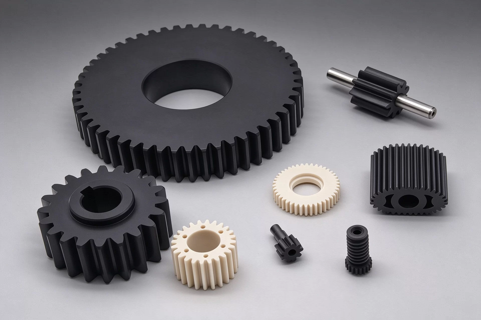
Gears & Motion Components
Custom spur gears, pinions and drive components for mechanical transmission. Material selection considers torque, speed, friction, noise and wear.
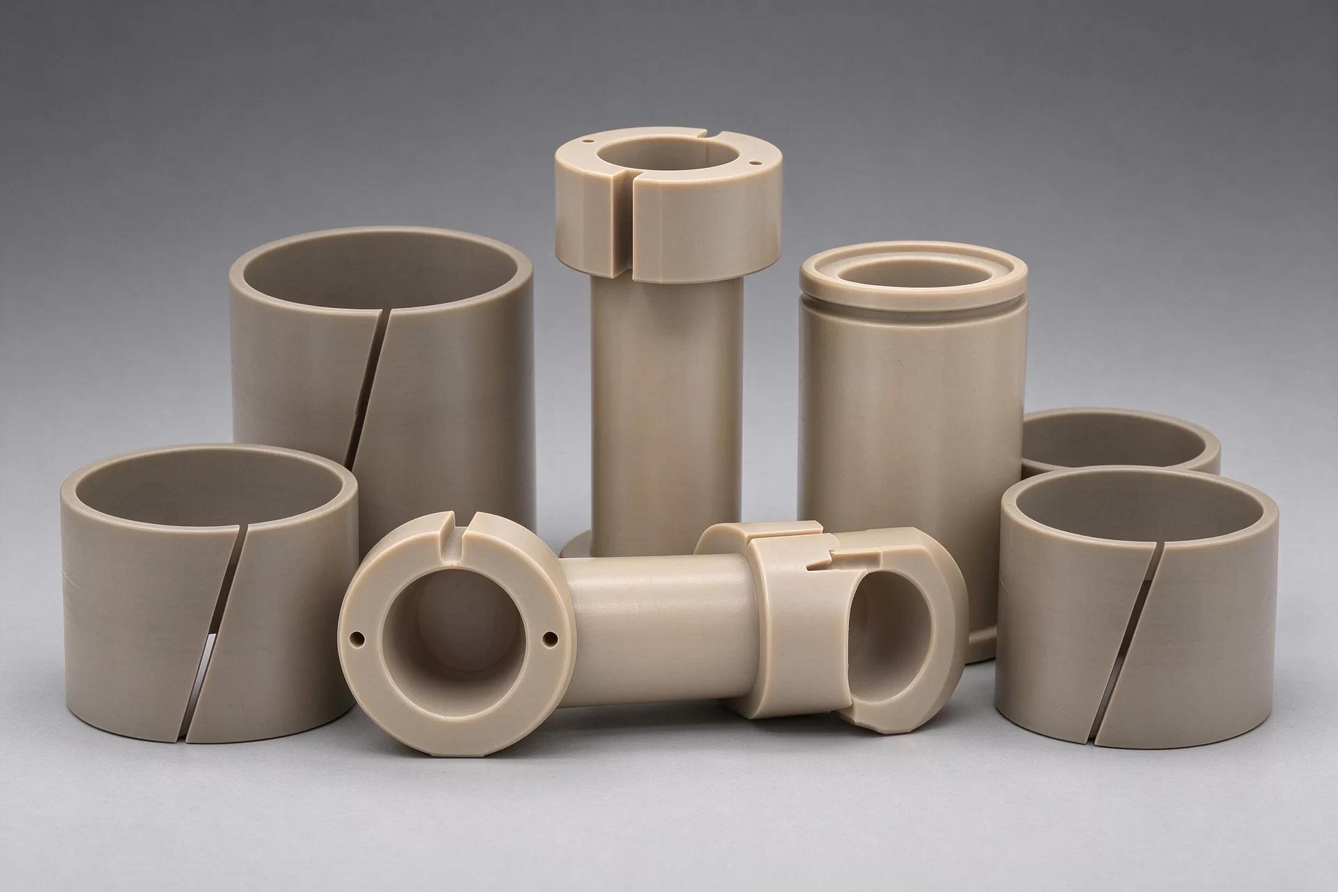
Bushings, Sleeves & Wear Parts
Machined bushings, split sleeves, spacers and thrust parts for shaft guidance and sliding contact. Design considers pressure, speed, lubrication, bore dimensions and running clearance.
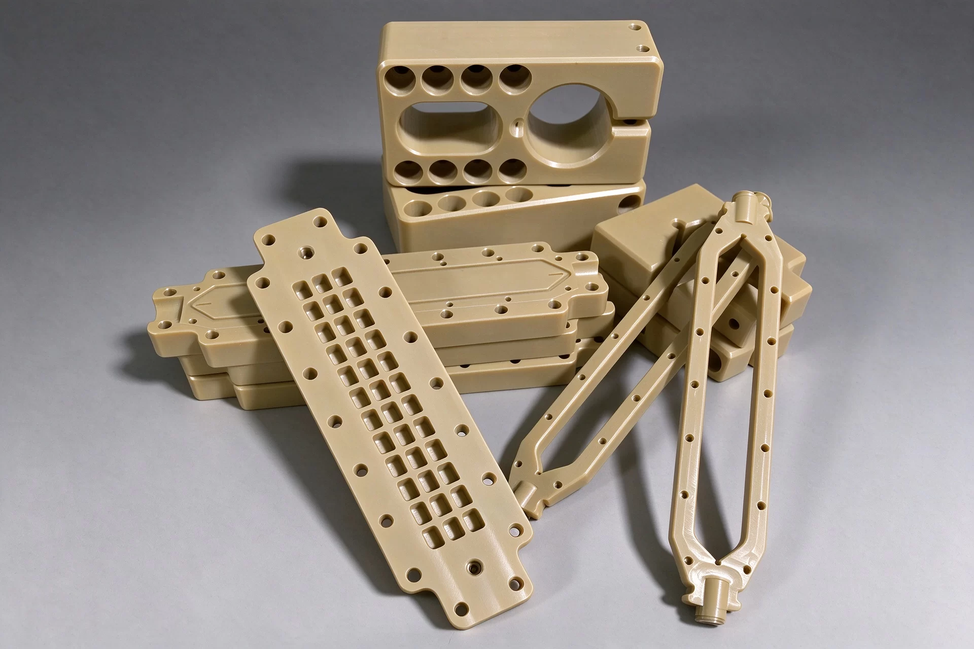
Guides, Fixtures & Insulating Supports
Custom wear pads, guides, mounting brackets and fixtures machined to drawing. Mounting features ensure alignment, while material selection addresses wear resistance and electrical insulation requirements.
capability
CNC Milling, Turning & Equipment Capacity
CNC milling and turning produce the faces, bores and profiles that connect your component to the machine. Combined operations add flats, holes and slots to cylindrical parts.
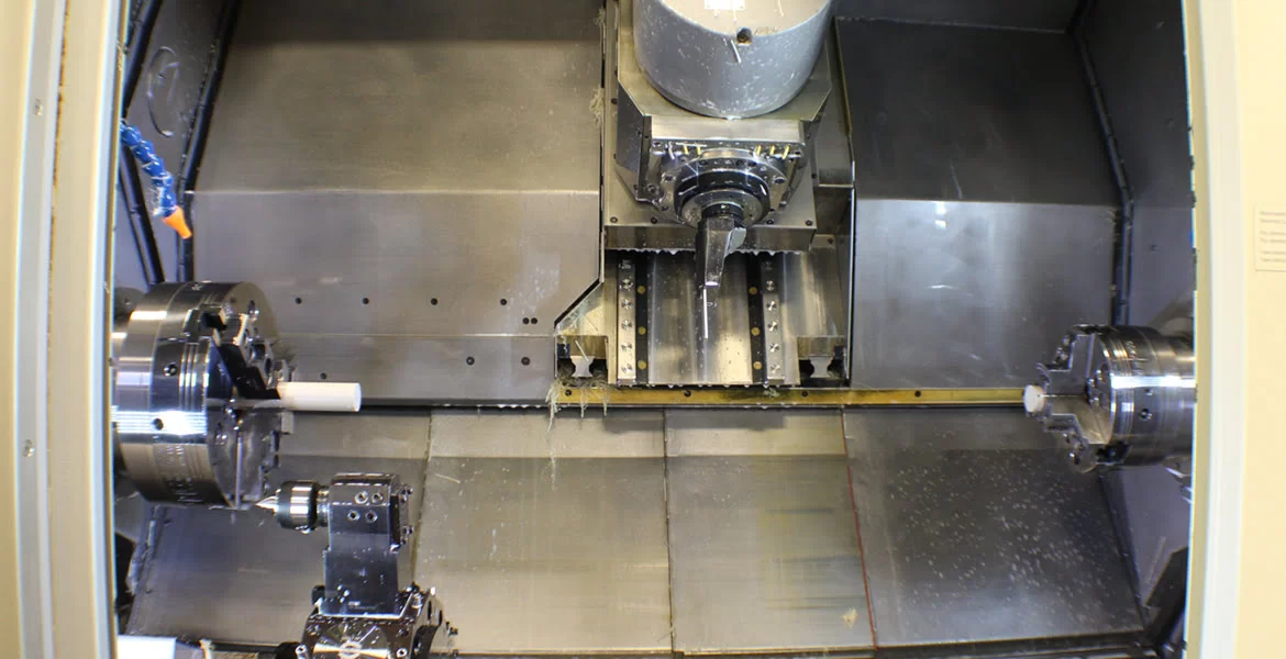
CNC Milling
Pockets, slots, mounting faces and bolt patterns from plate or block. Published nominal three-axis capacity is 1500 × 800 × 500 mm. Stock size, fixture clearance and cutter reach limit the usable part envelope. Deep pockets need accessible internal radii.
CNC Turning
Bores, shoulders, grooves and threaded profiles from rod or tube, with drilling for axial holes. Published nominal turning capacity is Ø431 × 990 mm. Chucking length, support and stock availability reduce usable dimensions. Long sleeves and thin walls can deflect during cutting.
Turn-Mill Features
Dual-spindle turn-mill equipment combines turned profiles with flats, cross-holes and off-axis features. Fewer transfers can help maintain their relationship to the bore. Tool access and workholding still determine the setup; not every feature is reachable in one operation.
Machine envelopes are not guaranteed finished-part sizes. Critical dimensions and tolerances are agreed by feature, material grade and setup. General tolerances do not establish a working clearance. CNC Plastic Machining Capabilities
Feature Analysis
Complex Machine Parts, Feature by Feature
The representative part geometries show where machining decisions affect assembly and operation. Your drawing defines the critical relationships; the material determines how they respond in service.
Gear Teeth, Roots & Shaft Fit
The tooth profile and root geometry determine contact and load transfer. The bore and drive feature connect that profile to the shaft. Tool access can constrain small roots and internal corners. Torque, temperature and the mating gear remain part of the specification.
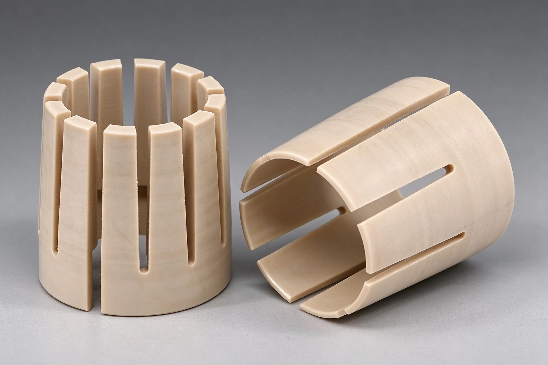
Bushing Bores & Thin Walls
Concentricity between the bore and outside diameter controls shaft alignment. Split features and thin walls can move under clamping. A measured bore at room temperature does not establish running clearance under heat or load. Thermal expansion, moisture and creep can change the operating fit.
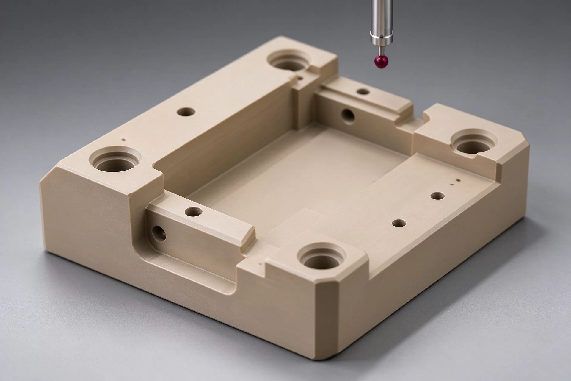
Pocketed Fixtures & Mounting Datums
Mounting holes, recessed faces and ribs must reference the surfaces that locate the fixture. Cutter reach limits deep pockets; internal corners retain a tool radius. Slender walls need support. Intersecting passages also need access for burr removal.
Material Selection
Material Options for Your Operating Conditions
Material fit depends on chemical exposure, temperature, load, motion and electrical duty together. Match the exact grade to your service conditions; a polymer family name alone does not establish suitability.
| Material | Component fit | Grade choice & limits |
|---|---|---|
| PEEK | Valve seats, backup rings, bushings and connector bodies. | Unfilled, glass-filled, carbon-filled and bearing grades serve different duties. Fillers change stiffness, wear and electrical behavior. Strong oxidizers need specific compatibility evidence. |
| PPS | Fluid-contact parts, guides and dimensionally stable supports. | Unfilled, glass-filled, carbon-filled and wear-modified grades differ. Thin edges and notches need care. Chemical compatibility depends on the complete formulation and exposure conditions. |
| PEI | Electrical housings, pin carriers and dry-side supports. | Useful where stiffness and insulation matter. Fluid compatibility and stress cracking can limit exposed parts; specify the electrical grade. |
| PAI | Loaded bushings, thrust parts and wear components. | Moisture conditioning affects dimensions. Hot water, steam and amines need particular review. Specify the filler and conditioning state. |
| PI | Hot supports, insulating spacers and specialized wear parts. | Grade, atmosphere and contact conditions govern suitability. Moisture, hot-water exposure and fillers can change the working fit. |
Carbon-filled grades may conduct electricity. Fillers can also change mating-surface wear. Temperature ratings alone do not establish life under sustained load.
Services
Manufacturing Services for Machinery Products
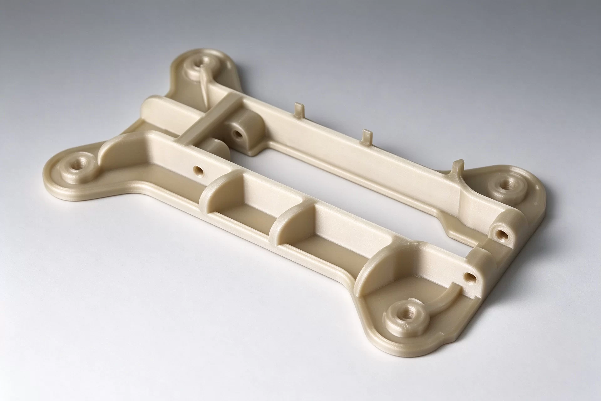
| Leverage the same speed, precision, and reliability in machining that you’re accustomed to at Great plastics but unlock advanced machining capabilities like tighter tolerances and volume pricing through our manufacturing network. Learn more→ |
|
 |
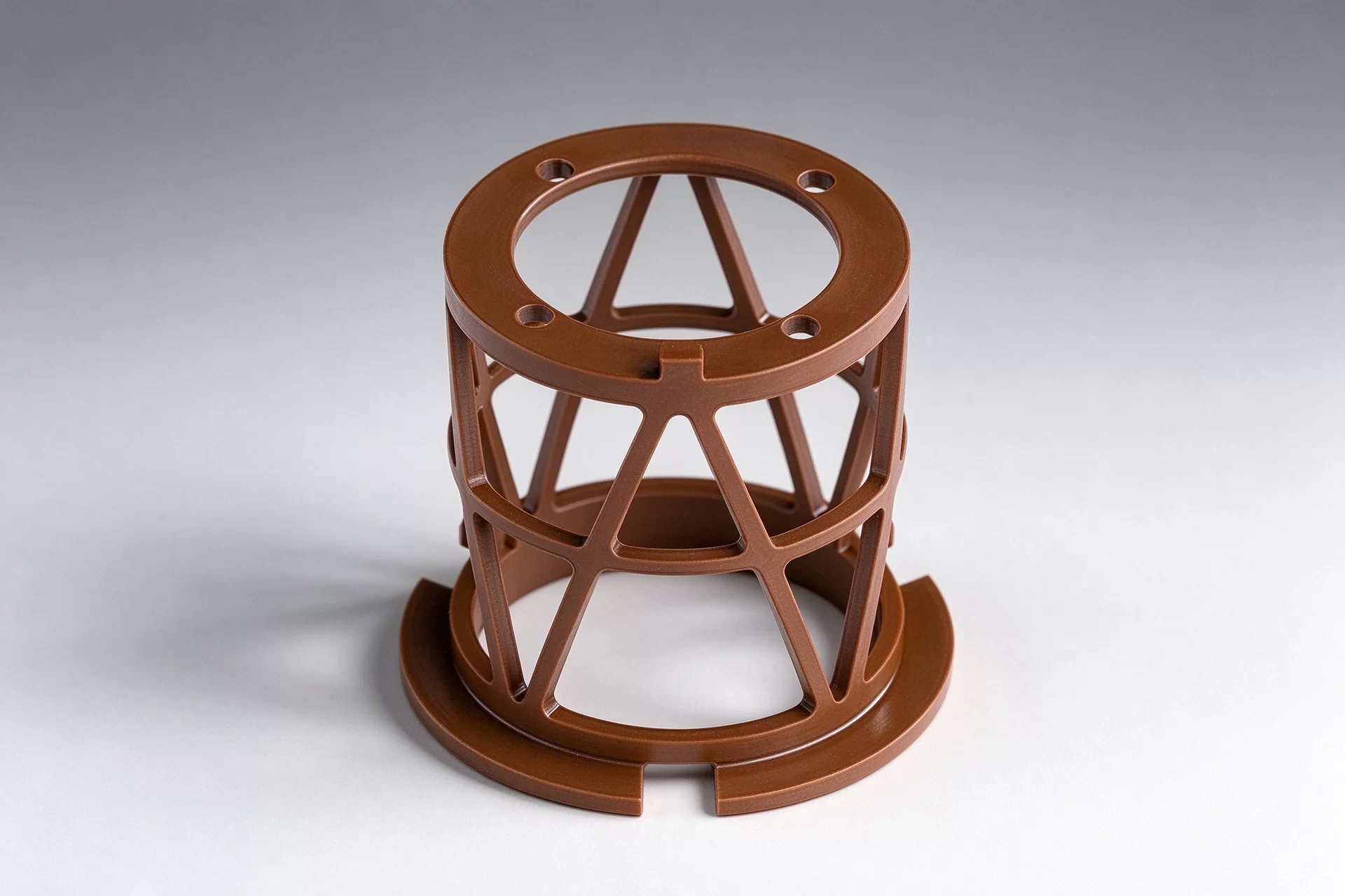
| Get affordable, high-quality molded parts and bridge tooling within days. With our free moldability consultation, the design and molding process is rapidly accelerated to save you time and money. Learn more→ |
|
 |
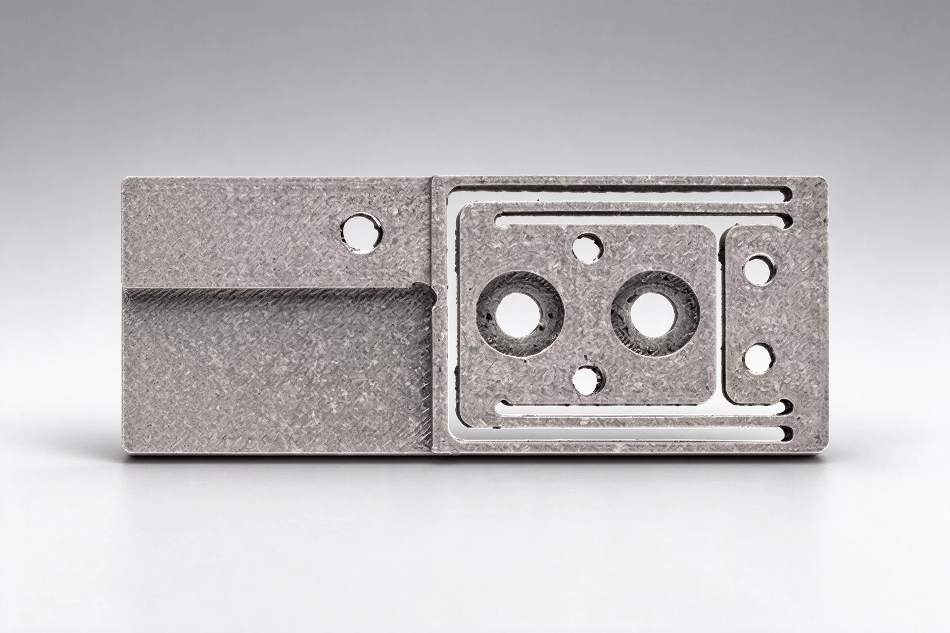
| Want quality parts and additive expertise at a single 3D printing source? Choose from fore different additive manufacturing technologies for cost-effective prototyping and highly precise, repeatable production parts. Learn more→ |
|
 |
How a Project Moves Forward
From Prototype to Repeat Production
From a functional prototype to small batches and repeat orders, your approved grade, drawing revision and critical features form the part definition.
Prototype & Application Validation
Review the drawing, material and critical features. Test machined prototypes for fit and performance under actual operating conditions.
Small-Batch Production
Use the approved sample, drawing revision, material grade and key dimensions as production references.
Repeat Supply
Maintain the approved material, drawing and inspection requirements. Revalidate changes to geometry, fillers or operating conditions.
